Loose steel flanges (Lap-joint flanges) GOST 12822 Pn 10
| Nominal diameter | Price, UAH without VAT | Availability in warehouse, pcs. | Reserve, pcs. | Weight, kg |
|---|---|---|---|---|
| DN 15 | 75.00 | 0 | 0 | 0.58 |
| DN 20 | 95.00 | 0 | 0 | 0.82 |
| DN 25 | 132.00 | 0 | 0 | 0.96 |
| DN 32 | 180.00 | 0 | 0 | 1.49 |
| DN 40 | 218.00 | 0 | 0 | 1.92 |
| DN 50 | 255.00 | 0 | 0 | 2.27 |
| DN 65 | 345.00 | 0 | 0 | 3.01 |
| DN 80 | 393.00 | 0 | 0 | 3.77 |
| DN 100 | 491.00 | 0 | 0 | 4.55 |
| DN 125 | 668.00 | 0 | 0 | 6.09 |
| DN 150 | 825.00 | 0 | 0 | 7.5 |
| DN 200 | 983.00 | 0 | 0 | 9.02 |
| DN 250 | 1317.00 | 0 | 0 | 11.3 |
| DN 300 | 1532.00 | 0 | 0 | 13.87 |
| DN 350 | 2174.00 | 0 | 0 | 18.02 |
| DN 400 | 2608.00 | 0 | 0 | 24.38 |
| DN 500 | 4565.00 | 0 | 0 | 33.25 |
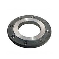
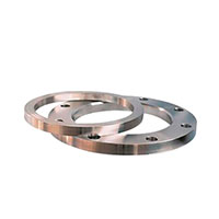
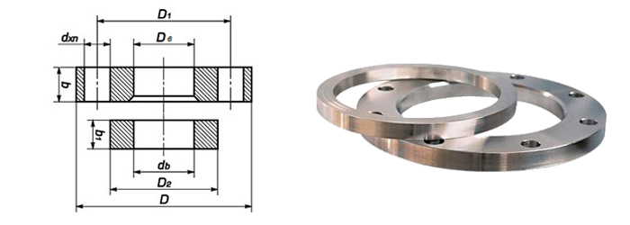
Lap-joint flanges PN 10, also known as loose flanges on a weld ring, are a construction consisting of two elements: an inner weld ring and an outer loose ring (flange). This type of flange is designed in accordance with the requirements of GOST 12822-80 standard and is widely used in pipeline systems due to its versatility and ease of installation.
The inner ring is welded to the pipe using two weld seams (internal and external), ensuring the joint's tightness. The outer ring remains loose and can rotate around the pipe, which simplifies the process of aligning the bolt holes during installation.
Advantages of lap-joint flanges GOST 12822-80
- Ease of installation: The free rotation of the outer ring allows easy alignment of the bolt holes of the opposite flanges.
- Simplicity of replacement: In case of damage or wear, the flange can be easily dismantled and replaced without the need for a complete disassembly of the system.
- Applicability in hard-to-reach places: The design is particularly convenient for installation in places with limited access or for frequent equipment repairs.
Attachment of lap-joint flanges
Bolts or studs with nuts and washers are used for attachment, selected based on the diameter of the holes in the flange. To ensure tightness between the flanges, gaskets made of materials resistant to the system's working medium are installed.
| DN | D | dв | b |
|---|---|---|---|
| 15 | 80 | 19 | 12 |
| 20 | 90 | 26 | 14 |
| 25 | 100 | 33 | 14 |
| 32 | 120 | 39 | 16 |
| 40 | 130 | 46 | 18 |
| 50 | 140 | 59 | 18 |
| 65 | 160 | 78 | 20 |
| 80 | 185 | 91 | 22 |
| 100 | 205 | 110 | 24 |
| 125 | 235 | 135 | 26 |
| 150 | 260 | 161 | 25 |
| 200 | 315 | 222 | 26 |
| 250 | 370 | 270 | 28 |
| 300 | 435 | 325 | 30 |
| 350 | 485 | 377 | 32 |
| 400 | 535 | 426 | 34 |
| 500 | 640 | 529 | 39 |
| Parameter name | Indicator |
|---|---|
| Nominal pressure PN, MPa (kgf/cm²) | 1.0 (10) |
| Connection type | свободный |
| Design features | плоский |
| Working environment | water, steam, non-aggressive liquids |
| Maximum working environment temperature, °C | 300 |
| Description | Material |
|---|---|
| Flange | Steel |